Now that you have the replacement shafts, it’s time to take apart your scanner! It’s relatively easy to do. There’s two ways to go about this, you can thoroughly disassemble your scanner OR, with the right tools, you can take off the front cover on it’s own.
Before you begin
- Have the replacement shafts on hand
- Make sure your scanner is unplugged!
- Remove the bottom tray
- A towel or a clean work surface
- You’ll need these tools:
- Phillips screw driver
- Flat head screw driver or a small pry tool
- Needle nose pliers
- Optional: Low Profile Offset Screwdriver Set or this one
- Optional: Mini Ratcheting Offset Screwdriver and Bit Set
The easy way…
This method is slightly more expensive as it requires the mini ratcheting screwdriver and ultra low profile offset screwdriver mentioned above. The plus side to this method is that you can complete the job much faster and there’s less risk of damaging your scanner or accidentally unplugging something.
Here are the tools you need:
Step 1
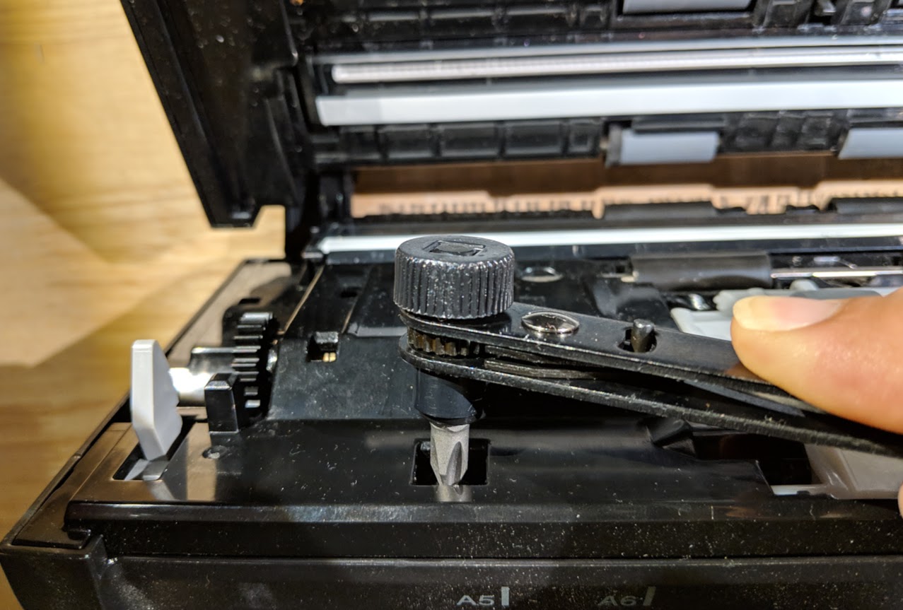
Use the ratcheting screwdriver to remove the top two screws. NOTE: I already owned a ratcheting screwdriver from Harbor Freight. The Neiko listed above may work better since it isn’t as deep, which should theoretically make removing the bottom right screw easier.
Step 2
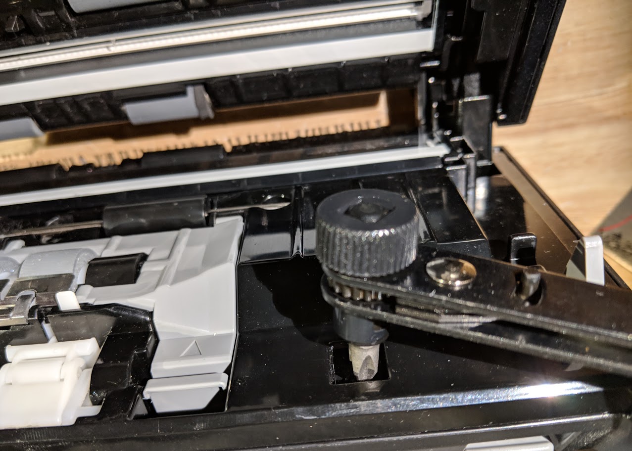
Remove the bottom right screw. This one is a bit tricky as there’s very little room. My ratchet screwdriver barely fits.
Step 3
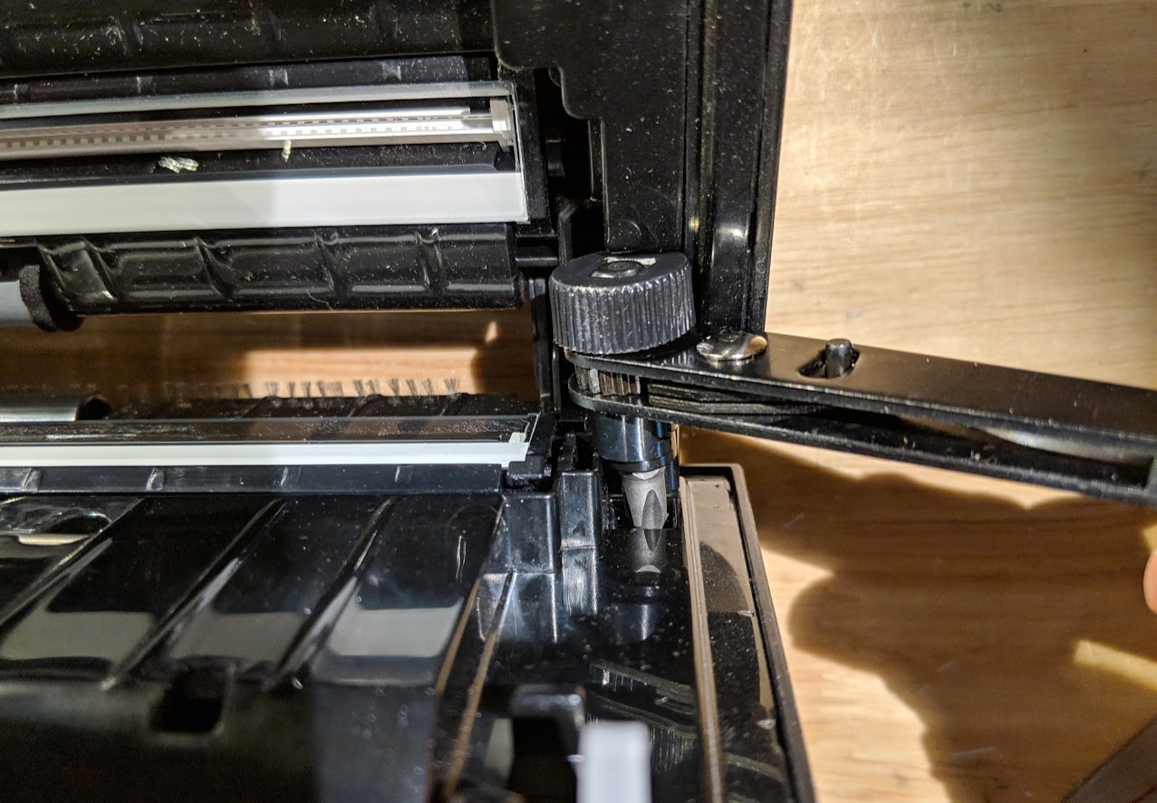
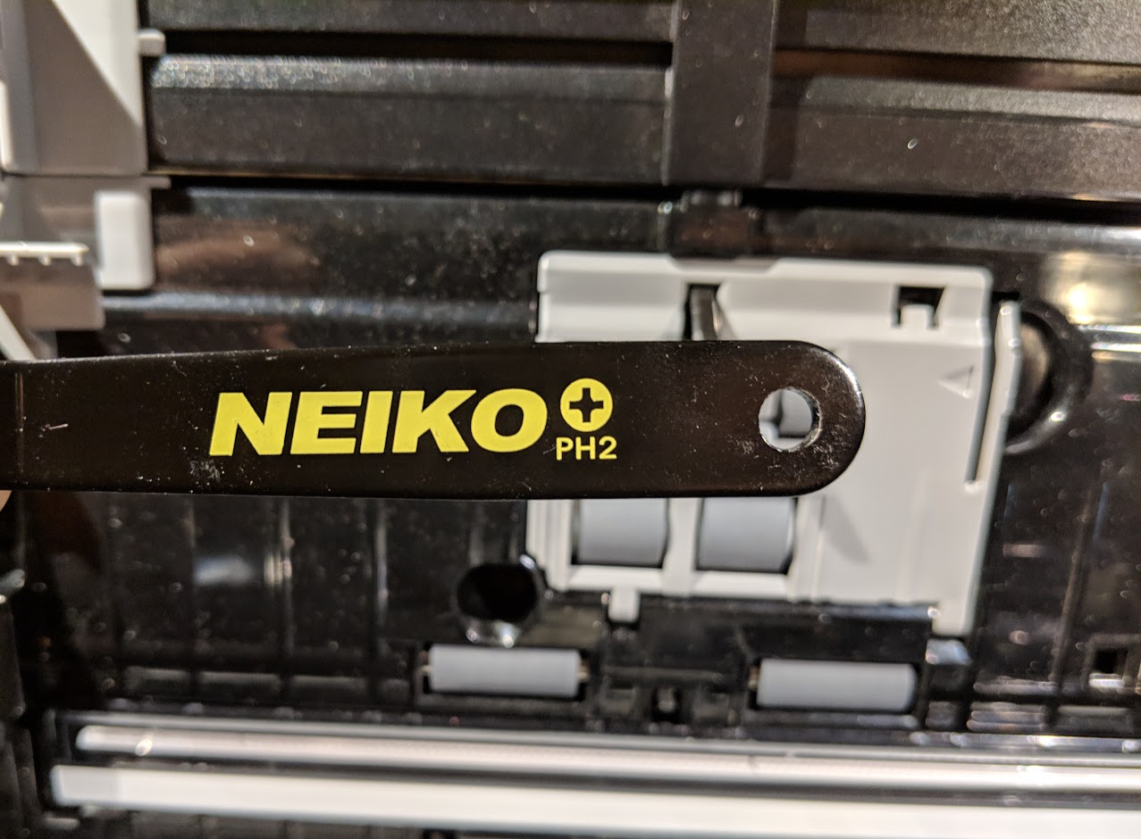
The bottom left corner screw will require use of the low profile screwdriver that’s marked PH2
Get the driver into place and start loosening the screw. Again, there isn’t much room, so you can only complete about 1/3 of a rotation at a time. Eventually it will back out enough where it will simply fall.
Step 4
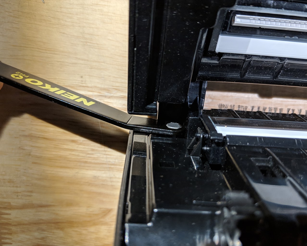
Once all the screws have been removed, pry the front cover apart using a thin screwdriver or other prying tool
Step 5
With the front cover off, you can skip to steps 8 through 10 below!
Reassembly
Reassembly is much easier. All you have to do is snap the front cover back on and replace all 4 screws. The bottom left screw can be difficult to get back into place, so you can either fight it back into place (takes some patience) or leave it off completely.
The more challenging way…
Step 1
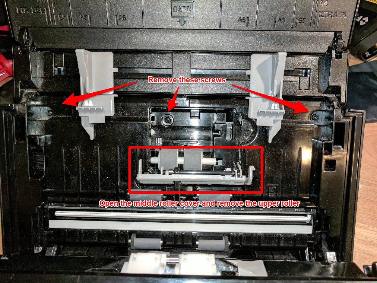
Pop open the front cover. Move the paper adjustments inward and pop open the middle cover. Remove the top roller. Now remove the 3 screws.
Step 2
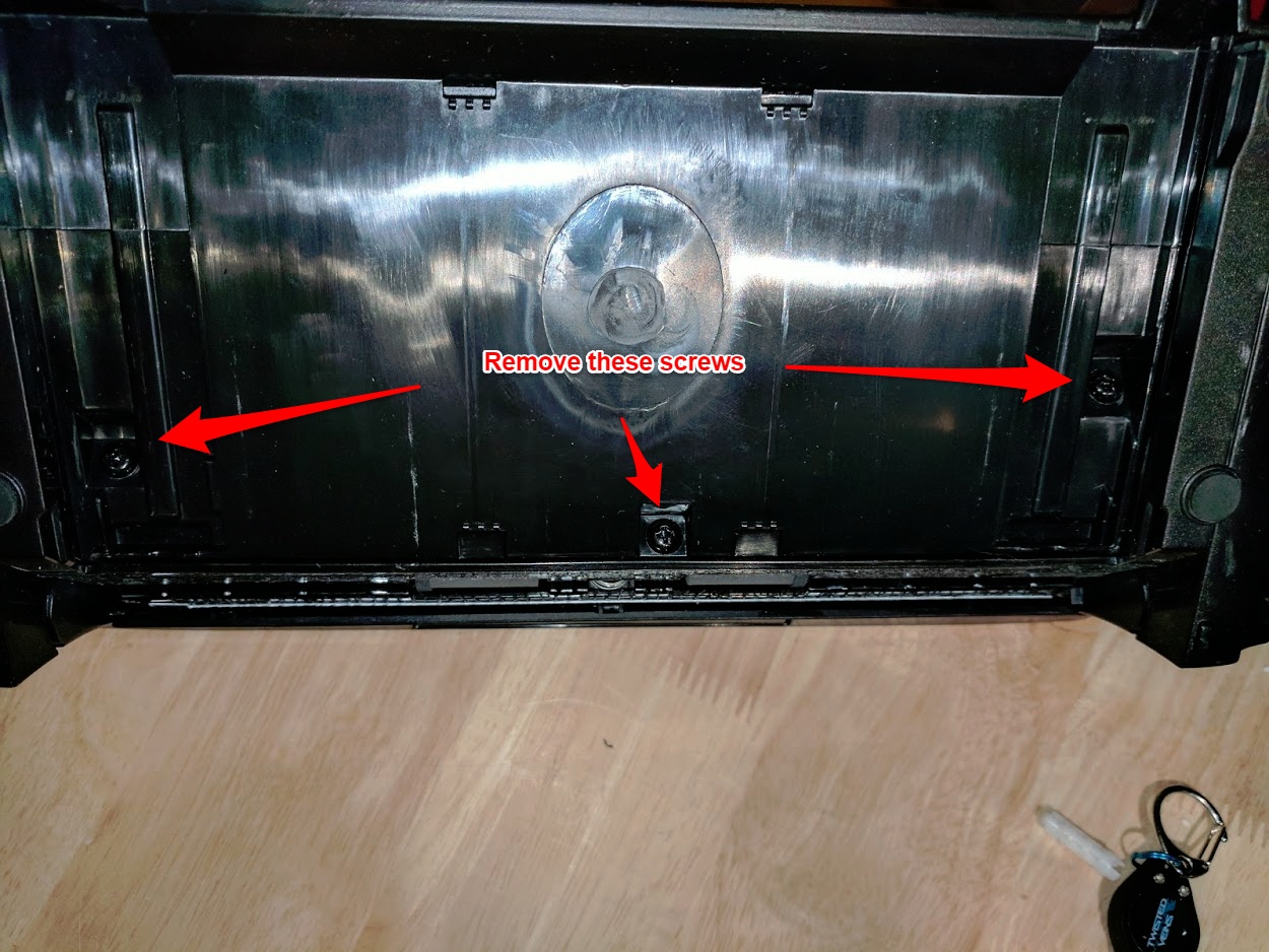
Turn the scanner over and remove the 3 screws that were previously covered up by the paper tray.
Step 3
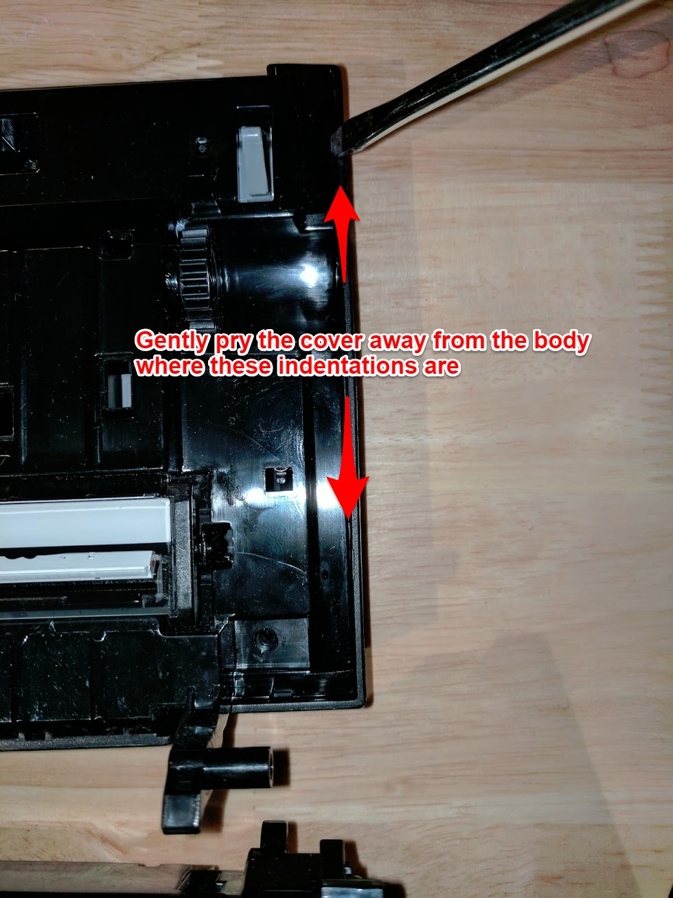
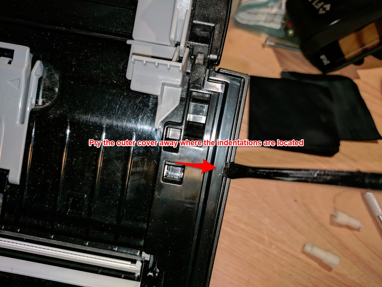
Pry away the outer cover. There’s indentations along the left and right sides. Insert your flat head screw driver here and twist it gently. This will separate the outer cover from the scanner itself. Carefully pull the cover away.
Step 4
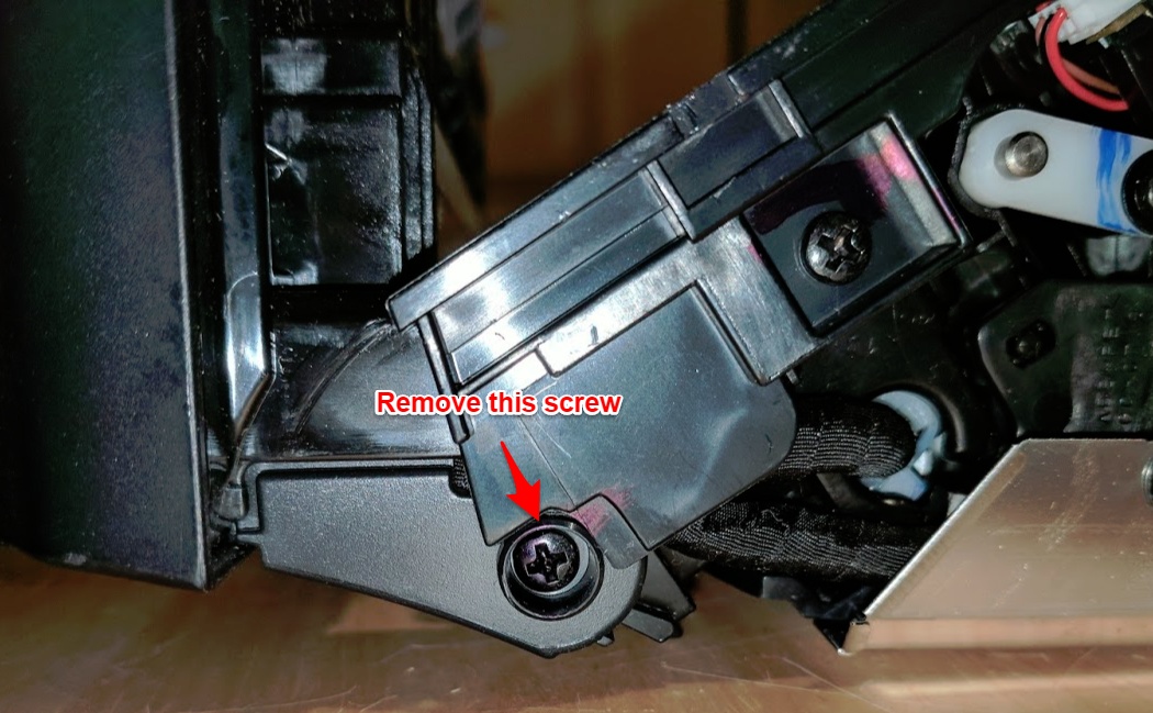
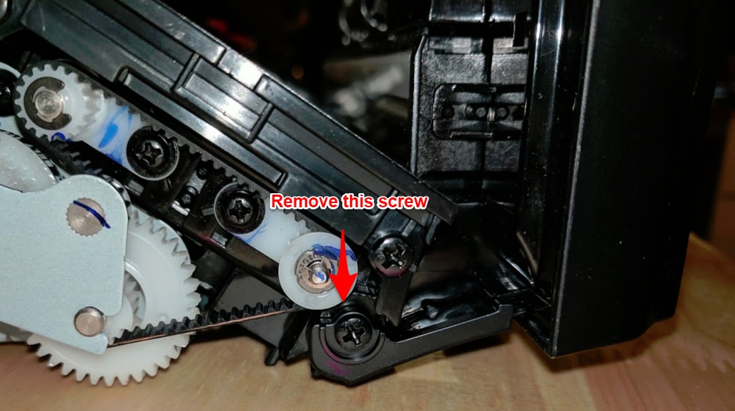
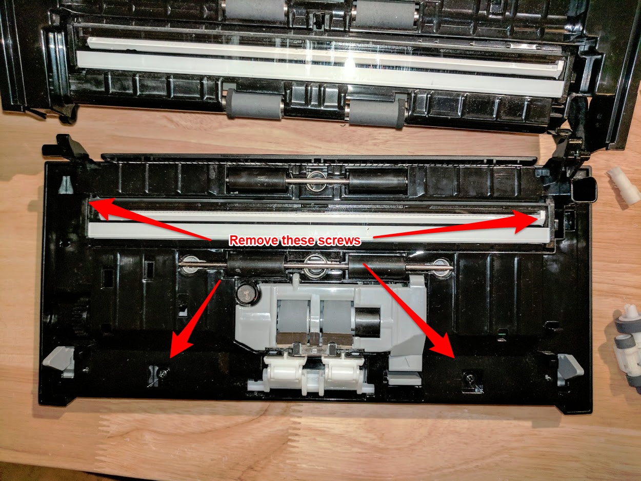
Remove the screws shown in these 2 pictures and then remove the 2 plastic covers that they hold in place.
Step 5
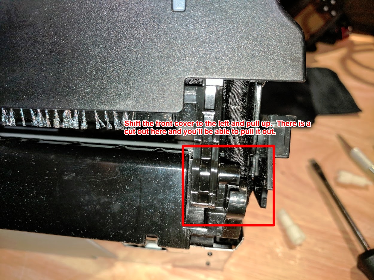
Once the screws and little plastic covers are off, you’ll be able to remove the front cover. This is accomplished by shifting the cover to the left and then pulling it UP. There’s a cut out in the right plastic hinge that allows this piece to slide out of place. Once it’s out, you can then move the cover to the right in order to get the opposite side out. Be VERY careful not to damage the wires that are routed along this side!
Step 6
With the front cover off, you can remove the 4 screws. Pop open the gray piece in the middle and remove the roller.
Step 7
Pry away the outer cover by inserting your flat head screwdriver into the indentations along the left and right sides. Gently twist it to separate the outer cover. You might also need to pry it apart at the small gap that runs along the top and bottom of the cover.
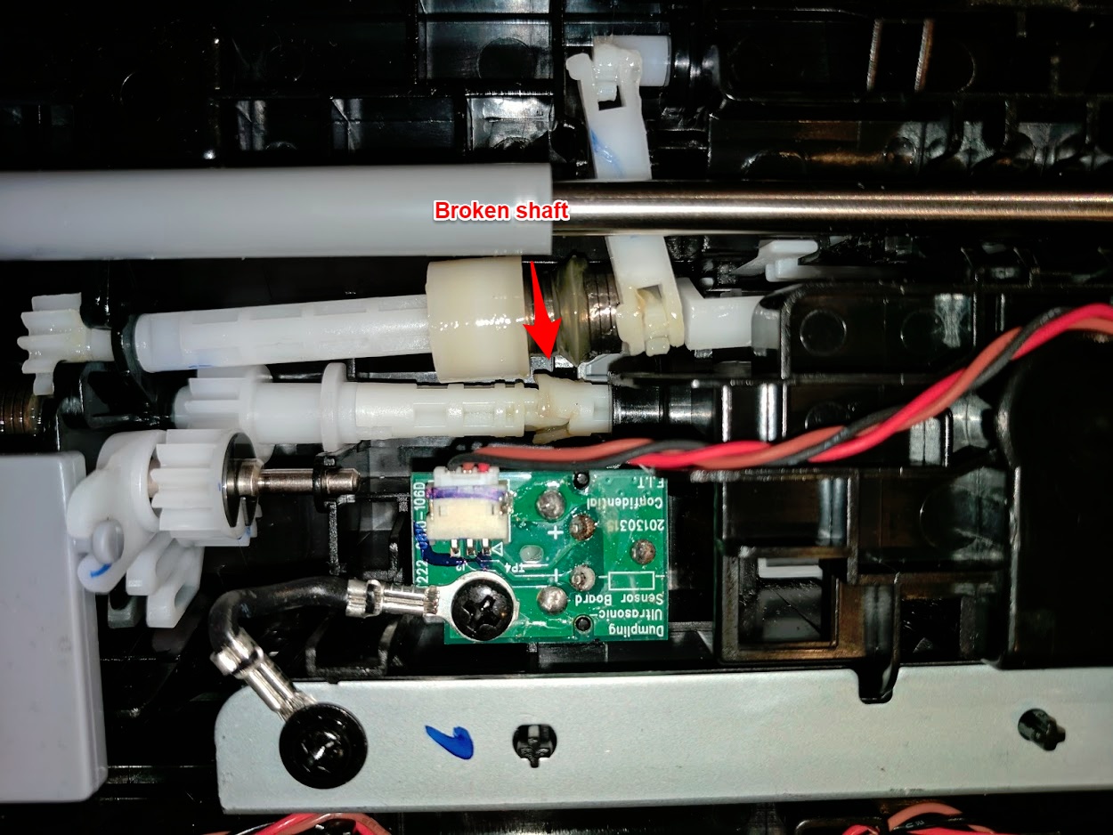
Step 8
With the front cover off, you can see the broken parts for yourself. One or both may be broken. They don’t usually break off completely – just splay apart as my picture shows. Go ahead and remove the broken shafts.
Step 9 – Read this one carefully!
Please exercise caution when executing the following steps! Several customers have reported breaking one of the two shafts during installation. I have repaired well over 150 of these scanners without breaking either one, so just exercise caution. If you break a shaft during installation please contact me for a replacement set at info@epsonscannerrepair.com
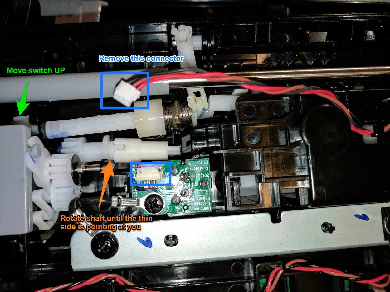
Now here’s the fun part. Carefully disconnect the little connector (blue square in the picture below). Then move the feed switch to the up (single sheet feed) position. This will allow you to rotate the shaft that outboard shaft connects to. Make sure the thin side is pointing towards you.
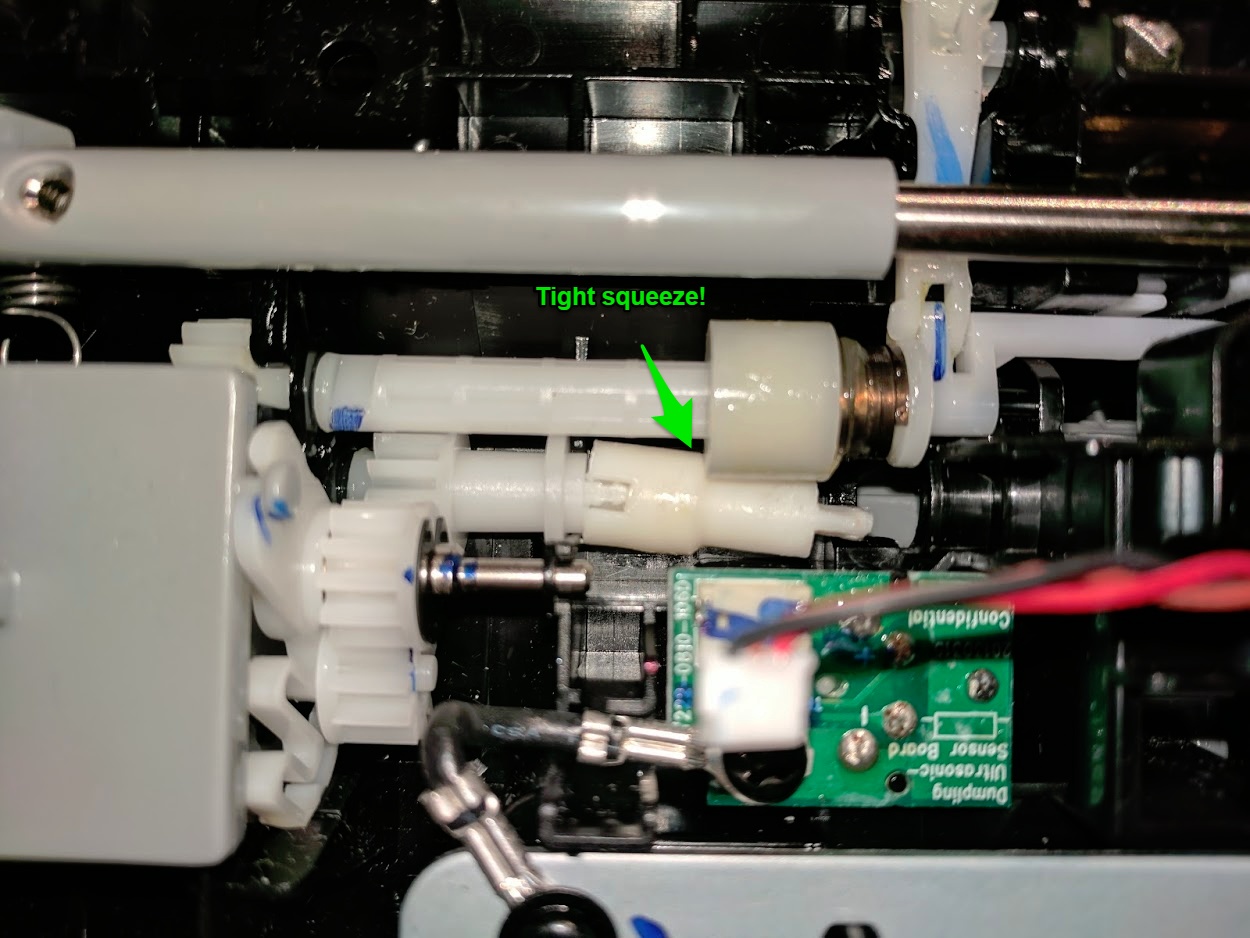
The shaft with the thicker end goes in first. You’ll have to angle it into place and then press down on the back (thinner) side. It’s a tight squeeze due to the thicker end, but rest assured it will go into place. You may have to use needle nose pliers to get it into position.
Here’s a short video that shows how to get it into place without breaking it:
And a picture of the shaft after installation:
Step 10
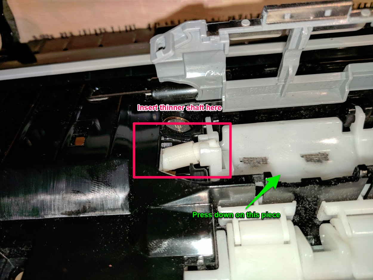
With the innermost shaft in place, you can then install the smaller one. Insert it into the hole and make sure it’s lining up with the other shaft. Once the shaft ends are lined up, press down on the plastic piece where the roller was located and insert the opposite end into place.
That’s it! Those last 2 steps might require some patience and perhaps some cursing, but rest assured, everything will fit into place.
Reassembly
Repeat the steps above in reverse. Make sure to plug in any connectors you may have disconnected. The connector for the main harness that goes into the board in the front cover may have worked itself loose (I don’t have a picture!), so make sure that it’s firmly in place. It might look like it’s connected, but it could be loose.